Evidence

Catalogue of Apollo landing evidence

Orbital imagery, lunar laser ranging, visible hardware, photo cross-checks, and NASA archives—each category links to primary releases you can open today. Mission tags connect rows to flight-specific dossiers.

6

Crewed landings

3

Apollo LRRR arrays

6

LROC featured sites

Introduction

This page is not an argument from authority: it is an index of artefacts, measurements, and documents that converge on the same six Apollo landing coordinates on the Moon.

Orbital cameras show hardware where logs say it was left. Lasers timed from observatories still bounce from the arrays astronauts deployed. Mission photography lines up, feature-for-feature, with modern terrain models.

Use the mission tags to jump to fuller mission pages, and follow the official links for the underlying data products.

For a plain-language overview of how these categories reinforce one another, read How we know before diving into individual catalogue rows.

Evidence

LRO and LROC orbital imagery

Narrow-angle camera strips and curated mosaics resolve each Apollo zone from above—often at sub-metre scales in later LRO campaigns.

Apollo landing sites from orbit — six-site LROC table

LROC narrow-angle thumbnail showing layered terrain near the Apollo 15 Hadley–Apennine landing site
Example product: Apollo 15 regional context from LROC; commissioning-era strips and later campaigns cover every Apollo zone (see LROC post 157).

Spotlight

Regional NAC context at every landing ellipse

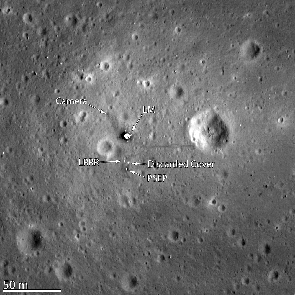
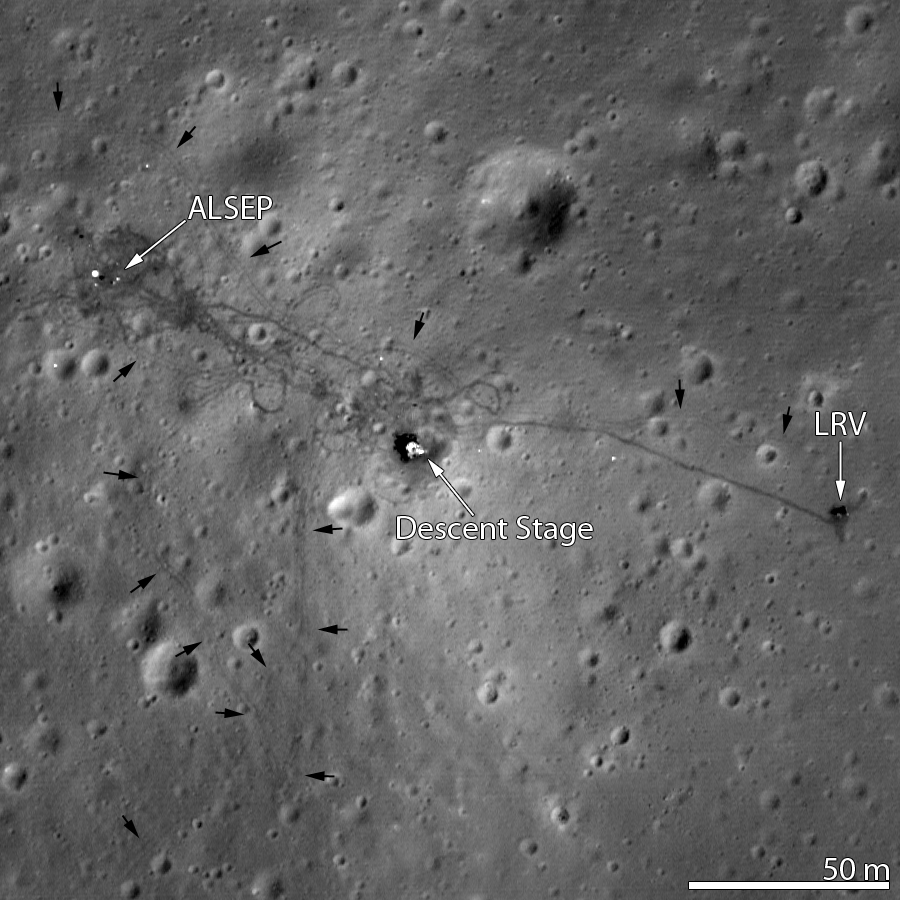
The July 2009 LROC “First Look” release published ~1 km-scale narrow-angle strips over each Apollo zone, giving a consistent baseline before later low-periapsis campaigns.

What this establishes

Robotic lunar orbiters re-imaged every crewed site with the same instrument family, letting analysts compare hardware signatures under known lighting geometry.

Official sources

Annotated LROC mosaic of Apollo 12 landing site with Intrepid, ALSEP, and Surveyor III labels
Official LROC release with printed call-outs—ideal reference for traverse-scale context.

Curated Apollo 12 & Surveyor 3 footprint map

LROC post 401 distributes an annotated mosaic at ~25 cm/px scale, naming astronaut craters and marking Intrepid, ALSEP, and Surveyor III on the Ocean of Storms.

What this establishes

Precision landing beside Surveyor III is not anecdotal: the orbital map matches the traverse described in mission reports.

Related missions

Official sources

LROC narrow-angle image of Apollo 11 landing site showing LM and experiments
Example: Goddard/LROC “A Stark Beauty All Its Own” product highlighting Tranquility Base hardware.

Low-periapsis LRO passes

After LRO entered a tighter mapping orbit, successive campaigns captured the descent stages and surface disturbance at higher resolution than the commissioning-era strips.

What this establishes

Improved ground sampling separates natural craters from geometric lander shadows as predicted by lighting models.

Official sources

Evidence

Surface hardware visible from orbit

Descent stages, experiment packages, and rover hardware cast predictable shadows; tracks and disturbed regolith persist in LROC frames.

LRO NAC image showing Apollo 11 lunar module descent stage and surface experiments

Spotlight

Descent stages still register at Tranquility Base

The Apollo 11 LM descent stage remains the tallest reflective object in the landing ellipse; LRO sees its deck, shadow, and surrounding blast zone.

What this establishes

Hardware dimensions and shadow length agree with engineering drawings when solar incidence and terrain slope are accounted for.

Related missions

Official sources

LROC mosaic of Apollo 12 site with LM, ALSEP, Surveyor III, and tracks labeled
White arrows on the official figure trace EVA paths between the three major artifacts.

Apollo 12 hardware beside Surveyor III

The fifty-first-anniversary LROC mosaic resolves Intrepid, ALSEP, Surveyor III, and astronaut tracks across the 275 m-wide field.

What this establishes

Two independent spacecraft (Surveyor and Apollo) appear in one LRO frame exactly where pre-mission targeting predicted.

Related missions

Official sources

LROC image of Apollo 15 site showing lunar module, ALSEP, LRV, and rover tracks
NASA GSFC Flickr release (6816337786) annotated by the LROC team.

Rover tracks and parked LRV at Hadley–Apennine

Low-altitude NAC data show wheel paths radiating from Falcon, tying traverse geology stops to orbital basemaps.

What this establishes

Surface mobility leaves a distinct regolith signature that persists and matches traverse timelines published in the surface journal.

Related missions

Official sources

LROC image of Apollo 17 lunar module Challenger at the landing site

Challenger descent stage at Taurus–Littrow

High-resolution passes capture the Apollo 17 LM in the valley floor, demonstrating consistent hardware signatures across mare and highland landing regimes.

What this establishes

The final Apollo landing site shows the same class of descent-stage photometry as earlier missions under different lithology.

Related missions

Official sources

Evidence

Retroreflectors and lunar laser ranging

Corner-cube arrays left by Apollo crews still return Earth-bound laser pulses—a quantitative, repeatable signature of human placement.

Apollo 15 Hasselblad photograph (AS15-88-11899) of the laser ranging retroreflector on the lunar surface
Surface documentation (Apollo 15) shows the finished array geometry used in geodesy models.

Spotlight

Apollo laser ranging retroreflector arrays

Apollo 11, 14, and 15 each deployed corner-cube packages designed for Earth–Moon time-of-flight ranging; they remain operational targets for global observatories.

What this establishes

Independent labs measure range residuals consistent with reflectors sitting at the published selenographic coordinates—not with a remote natural outcrop.

Official sources

NASA photograph of the Apollo 11 lunar laser ranging retroreflector experiment on the lunar surface
NASA archive image of the Apollo 11 laser ranging experiment; terrestrial stations still range the Apollo arrays today.

Terrestrial laser stations still acquire returns

Facilities such as APOLLO (Apache Point) and legacy MLRS hardware fire short pulses and statistically detect photons from the Apollo arrays alongside Soviet Lunokhod reflectors.

What this establishes

Any researcher with allocated telescope time can attempt the same measurement—no proprietary “mission-only” channel is required.

Official sources

Evidence

Apollo surface photos vs modern orbiters

Pairing Hasselblad panoramas with LRO passes ties 1960s–70s surface perspective to terrain geometry measured decades later.

Buzz Aldrin stands beside the lunar module during Apollo 11 EVA
1969 — Hasselblad surface perspective (Apollo 11).
LROC narrow-angle view of the same landing region decades later
2010s — LRO NAC geometry of the same terrain.

Spotlight

Crew Hasselblad frames overlaid on LRO geometry

Panoramas taken on the surface align, within known camera pointing, to slopes and craters in modern NAC orthoprojections—closing the loop between human vantage and robotic cartography.

What this establishes

When terrain relief matches at two epochs, the simplest explanation is a shared real surface—not unrelated studio sets.

Related missions

Official sources

Same landing zone: surface photography and robotic narrow-angle imagery are co-registered by LROC investigators.

Evidence

NASA mission archives and documentation

Flight plans, debriefs, telemetry archives, and surface journals preserve the operational record alongside the physical traces.

Apollo 11 bootprint in lunar regolith

Apollo Lunar Surface Journal

Transcript-level commentary ties Hasselblad magazines, timeline segments, and traverse maps to the raw voice loops—an annotated public companion to the flight data.

What this establishes

Primary speech, photo numbers, and map figures interlock; errors would surface quickly in this cross-linked corpus if the underlying timeline were fictitious.

Official sources

Mission Control Houston during Apollo 11 lunar surface EVA (NASA S69-39593)
Flight operations documentation anchors the contemporaneous engineering record.

NASA mission pages & NSSDCA data registry

Each flight retains authoritative summaries, press kits, and pointers into the National Space Science Data Center for experiment data sets and imagery masters.

What this establishes

Institutional archives preserve enough detail—downlink formats, PI responsibilities, and tape logs—for third parties to audit the program’s outputs.

Official sources

Apollo 11 mission insignia

LROC RDR / CDR product documentation

Calibrated narrow-angle camera pipelines, pointing kernels, and release notes explain how orthomosaics and DTMs are produced—supporting reproducible science on Apollo sites.

What this establishes

Open documentation of calibration steps lets independent teams reprocess raw observations and confirm feature measurements.

Official sources

Related guides

Open the interactive Moon map to place each artefact in geographic context, read how the evidence lines converge, or browse mission-by-mission dossiers. For LRO narrow-angle coverage of every crewed landing, use Apollo landing sites from orbit—then audit claims in the primary source index.